
PHONE: (847) 253-6000
TOLL FREE: (800) 52-MOTOR

Choosing the best Permanent Magnet DC Motors in 2026 starts with the application, not a catalog headline. A small conveyor, a pump, and a mobile platform can demand very different torque, speed, and control behavior. That difference matters. The motor must suit its load during startup, steady operation, and repeated stops—not merely match a rated voltage.
This guide explains how to compare the factors that shape real-world performance: required torque and speed, supply voltage, duty cycle, available space, and operating temperature. It also looks at efficiency, brush wear, noise, maintenance access, and compatibility with controllers. These details can be easy to overlook. For example, a motor that handles a brief load may overheat during continuous use, while an undersized shaft can complicate an otherwise sound design.
A useful selection process begins with measurable requirements and checks them against manufacturer data, including torque curves, thermal limits, and service guidance. Where possible, compare specifications under similar test conditions; headline ratings alone can hide important differences. The lowest purchase price is not always the lowest operating cost, but a premium model is not automatically the right choice either. The first shortlist may need revision. That is normal. Treat estimates as estimates, confirm critical details with the supplier, and consider testing the motor under representative loads before committing. This practical approach helps buyers weigh performance, reliability, and lifecycle needs with fewer assumptions.
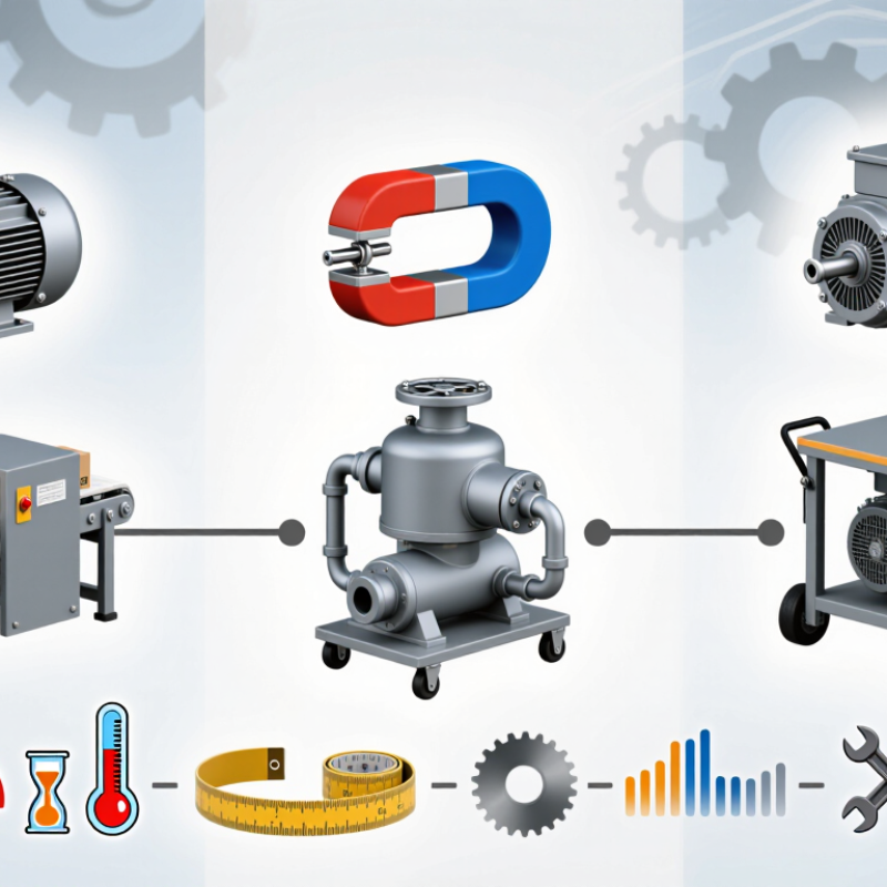
A permanent magnet DC motor should be selected for the job it must perform, not just its power rating. Define the load, required speed, available supply voltage, and duty cycle before comparing motors. A small conveyor that starts under load needs different torque from a fan that runs steadily. Note how often the motor starts, stops, or reverses. These details affect heating and performance. A rating alone does not tell the whole story.
Tips: Measure the actual load if possible. Record startup current, shaft speed, and ambient temperature during a typical operating cycle. Leave room for brief overloads, but do not oversize without reason; an oversized motor can waste space and complicate control. Keep a simple log. It helps.
Check the mounting space, shaft dimensions, and cooling conditions at the installation site. Dust, restricted airflow, or frequent low-speed operation may raise motor temperature. Confirm the controller can supply the required startup current and handle the intended speed range. I have found that early load estimates can be optimistic. Recheck them after testing a prototype, especially if the mechanism binds or the load changes during operation. A few careful measurements can prevent a motor that looks suitable on paper from struggling in service.
Use this table to define initial requirements before comparing motors. The example ranges are screening values, not universal specifications; confirm actual shaft speed, continuous and peak torque, current, temperature rise, and service life against the specific design.
| Application | Load and Motion Profile | Typical DC Supply | Indicative Output Range | Duty and Starting Requirements | Operating Environment | Key Selection Checks |
|---|---|---|---|---|---|---|
| Compact positioning actuator Small gates, adjustable fixtures, or linear mechanisms |
Intermittent movement, frequent starts and stops, and potentially high torque near the end of travel. A gearbox or lead screw may be required. | 12 V or 24 V, subject to the available power supply and wiring limits | Approximately 100–500 rpm at the motor shaft before any gearbox; size torque from the mechanism’s measured load and required acceleration. | Often intermittent operation. Check start-up and stall current, acceleration time, peak torque, and the number of starts per hour. | Check ambient temperature, dust or moisture exposure, mounting orientation, and any enclosure requirements. | Confirm gearbox ratio, backlash, end-stop strategy, peak current capability, and whether the motor can tolerate a brief stall. |
| Small conveyor or feed mechanism Light-duty material handling |
Steady rotation with load changes during starting, loading, or jams. Required torque depends on belt tension, roller size, and conveyed mass. | 24 V or 48 V are common system choices; match the motor to the actual supply and controller. | Approximately 50–300 rpm at the driven shaft is a useful initial range for many small mechanisms; calculate torque from the conveyor load. | May require continuous operation. Verify continuous torque, start-up torque, thermal limits, and recovery behavior after a jam. | Consider dust, vibration, ambient temperature, and whether the motor is near washdown or corrosive materials. | Check continuous-duty rating, gearbox service factor, current under load, speed regulation, and protection against overload. |
| Metering or small fluid pump Low-flow dosing and circulation systems |
Continuous or controlled-speed rotation. Pump torque can vary with pressure, fluid viscosity, and operating point. | 12 V or 24 V for many compact systems; higher-voltage supplies may be used in larger equipment. | Approximately 10–300 rpm at the pump shaft for many low-speed metering setups; establish the actual speed and torque from the pump curve. | Determine whether the pump runs continuously or in cycles. Check start-up under pressure and the allowable speed range. | Assess ambient temperature, condensation, fluid leakage, and the separation required between the motor and wetted components. | Match motor torque to the pump’s pressure and viscosity range; verify speed control, current margin, sealing, and fluid compatibility of nearby parts. |
| Mobile equipment auxiliary drive Small powered mechanisms on carts or vehicles |
Variable-speed operation with changing load, vibration, and frequent acceleration or reversal depending on the function. | 12 V or 24 V systems are common; confirm voltage sag and available current during simultaneous loads. | Speed is application-specific; select motor and any reduction gearing from required wheel, roller, or mechanism speed and load. | May experience repeated starts and brief overloads. Evaluate peak current, continuous current, duty cycle, and braking or reversing requirements. | Account for vibration, shock, ambient temperature, dust, moisture, and the vehicle’s electrical transients. | Check controller current limits, fuse and cable sizing, mounting strength, thermal performance, and the required environmental protection. |
| Portable appliance or compact mechanism Battery-powered consumer or service equipment |
Compact, often high-speed operation with a load that may vary over each operating cycle. | Typically a battery-dependent low-voltage supply, such as 6–24 V; use the battery’s full charge and discharge range. | Motor speeds may range from hundreds to several thousand rpm; determine the operating point from the load and any transmission ratio. | Usually intermittent, but short cycles can still cause heating. Check repeated-start performance and current drawn at low battery voltage. | Consider restricted airflow, hand-held temperature limits, impact exposure, and expected storage conditions. | Balance size, efficiency, noise, battery runtime, winding temperature, and the controller’s ability to handle inrush current. |
| Fan or blower Ventilation and compact air-moving equipment |
Rotating load whose torque demand generally rises substantially as speed increases; airflow and pressure requirements define the operating point. | 12 V, 24 V, or 48 V depending on the system design | Often hundreds to several thousand rpm; use the fan curve and required airflow and static pressure rather than selecting by speed alone. | May run continuously. Verify motor temperature at the actual fan operating point and account for restricted or blocked airflow. | Check inlet-air temperature, dust, humidity, ventilation around the motor, and any required filtration. | Confirm the fan curve, continuous thermal rating, speed-control range, acoustic limits, and protection against blocked airflow. |
Define the load, required speed, supply voltage, and duty cycle. Note how often the motor starts, stops, or reverses.
A rating alone may miss startup torque, heat buildup, or changing loads. A loaded conveyor and a steady fan need different performance.
Record startup current, shaft speed, and ambient temperature. Measure the actual load when possible. Keep a log.
Tight mounting space, dust, and restricted airflow can increase temperature. Frequent low-speed operation may also affect cooling.
Confirm it can provide the required startup current and support the intended speed range. Include the actual controller and cables in testing.
Test each motor under its real duty cycle. Record current, speed, torque, winding temperature, and voltage during repeated loaded runs. Small details matter.
Ask for raw readings, equipment details, traceability, and stated tolerances. Check that the tested sample matches the production design.
Bench results may change with real wiring, load shifts, or imperfect alignment. Test it again. My first load estimate may be wrong.
Choosing the best Permanent Magnet DC Motors in 2026 begins with a clear understanding of the application. Define the required operating conditions, including load, duty cycle, available space, power supply, and exposure to heat, dust, or moisture. Then compare key performance ratings—power, speed, torque, and efficiency—to ensure the motor can meet both normal and peak demands without being unnecessarily oversized.
Look beyond the ratings to examine construction, control options, and suitability for the installation environment. Consider reliability, applicable quality and safety requirements, maintenance needs, and total cost of ownership rather than purchase price alone. Finally, narrow the options to a shortlist and validate them through practical testing under representative conditions. Reviewing technical documentation, support arrangements, and supplier consistency can help confirm that the selected motor will perform dependably throughout its intended service life.