High Torque in Tight Envelopes
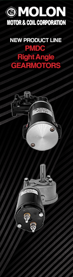
PMDC Right Angle Gearmotors
Engineered 12V, 24V, and 90V DC right-angle drive solutions for global OEM manufacturing programs.
Contact Us

Technical Sourcing & OEM Application Guide
In modern industrial, commercial, and medical equipment manufacturing, space optimization is no longer just a design parameter—it is a critical competitive advantage. When design engineers need to deliver maximum continuous output torque within tight mounting envelopes where axial length is strictly limited, standard inline or parallel shaft gearmotors often fail to fit. This is where PMDC Right Angle Gearmotors prove irreplaceable.
By coupling a high-flux-density Permanent Magnet DC (PMDC) armature to a high-efficiency 90-degree gear housing (utilizing precision worm gears, helical-bevel, or right-angle spur topologies), PMDC right angle gearmotors translate high-RPM low-torque electrical power into low-RPM high-torque mechanical power at a right angle to the motor centerline. The resulting 90-degree drive orientation allows machine designers to position the motor flush against chassis walls, under conveyor lines, or inside compact medical chassis without wasting valuable axial depth.
At Molon Motor & Coil Corporation, we have engineered, wound, and manufactured custom fractional horsepower (FHP) motors and gearmotors in Illinois, USA since 1954. Drawing on seven decades of practical electro-mechanical manufacturing, this technical guide examines the underlying physics, procurement criteria, future trends, and application design parameters for PMDC right angle gearmotors to assist OEM design engineers and procurement directors globally in making data-driven sourcing decisions.
To evaluate a PMDC right angle gearmotor for long-term OEM reliability, one must look beyond superficial speed-torque curves and understand the electro-mechanical interaction between the PMDC motor section and the right-angle reduction unit.
A Permanent Magnet DC motor utilizes ceramic or rare-earth permanent magnets attached to the interior of the stator housing, creating a continuous, constant magnetic field. The rotating armature consists of copper magnet wire wound around a laminated steel core, connected to a mechanical commutator with carbon or graphite brushes. When DC voltage (typically 12VDC, 24VDC, 90VDC, or 180VDC) is applied, current flows through the brushes into the armature coils, generating an electromagnetic field that reacts against the stator magnets to create smooth rotary motion.
Key technical benefits of the PMDC motor section include:
The defining feature of a PMDC right angle gearmotor is its gearbox configuration. The two primary mechanisms employed in fractional horsepower applications are:
Selecting the optimal PMDC right angle gearmotor platform requires balancing mechanical envelope constraints, duty cycle, ambient operating temperature, shaft loading, and unit target costs. Molon offers fully customizable platforms tailored for OEM volume production programs.
Ultra-compact 90-degree profile designed for automated vending, commercial beverage dispensing, and compact HVAC damper actuation.
Contact Us for Specs →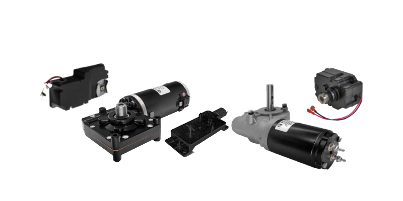
Engineered with hardened steel worm shafts and phosphor bronze gearing for continuous conveyor, agricultural feeding, and industrial machinery.
Contact Us for Specs →
Precision-built under medical quality systems for patient positioning beds, surgical pumps, and laboratory sample analyzers.
Contact Us for Specs →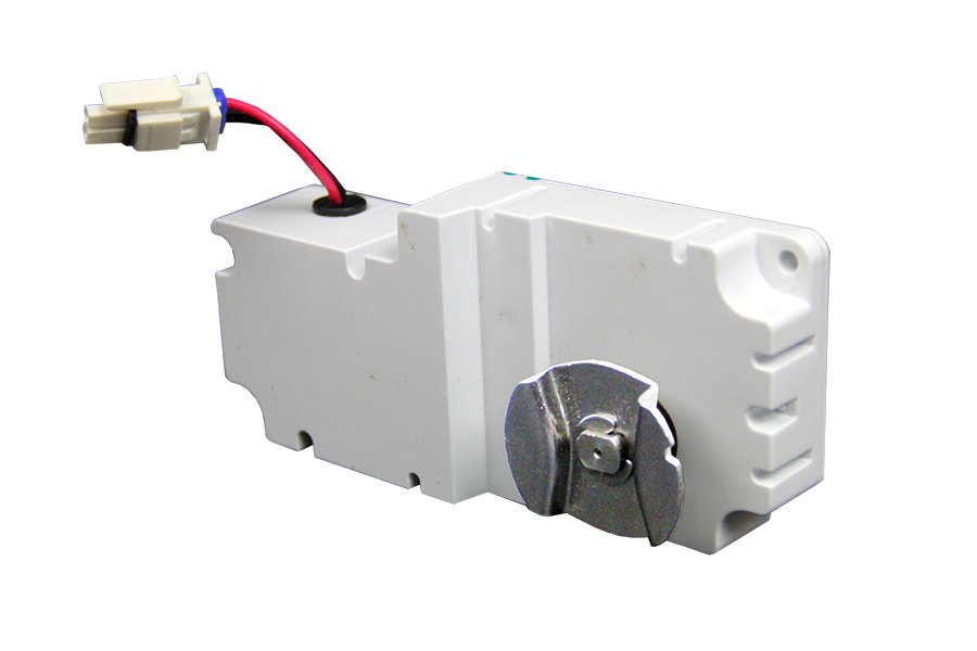
Harsh environment right-angle actuators built for outdoor agricultural spreaders, marine winches, and ice maker augers.
Contact Us for Specs →The table below provides engineering decision parameters across Molon's primary fractional horsepower gearmotor platforms, allowing OEM purchasing teams to compare technical capabilities side-by-side.
| Design Criteria | PMDC Right Angle Gearmotors | PMDC Parallel Shaft | Brushless DC (BLDC) Right Angle | PSC AC Right Angle |
|---|---|---|---|---|
| Input Voltage Options | 12 VDC, 24 VDC, 90 VDC, 180 VDC | 12 VDC, 24 VDC, 90 VDC, 180 VDC | 12 VDC, 24 VDC, 48 VDC | 115 VAC, 230 VAC (50/60 Hz) |
| Speed Control Simplicity | Very High (Simple PWM / DC Voltage variation) | Very High (Simple PWM / DC Voltage variation) | Requires dedicated electronic drive controller | Fixed speed (Requires AC inverter for VFD) |
| Self-Locking Capability | High (In high reduction worm ratios >30:1) | Low (Back-drivable in most spur layouts) | Depends on gearbox type (Worm vs Bevel) | High (If equipped with worm gearbox) |
| Mechanical Envelope Profile | Ultra-Flat (Flush offset 90° shaft output) | Long axial length, parallel offset output | Ultra-Flat 90° shaft output | Moderate-to-large axial profile |
| Typical Operating Life | 2,000 to 5,000 Hours (Brush limited) | 2,000 to 5,000 Hours (Brush limited) | 15,000 to 30,000+ Hours (Bearing limited) | 10,000 to 25,000 Hours (Bearing/Capacitor limited) |
| Upfront System Cost | Low to Moderate (Optimal ROI) | Low to Moderate | Moderate to High (Electronics cost) | Low to Moderate |
When specifying a PMDC right angle gearmotor, engineering teams often run into two technical topics that require deep physical modeling: gearbox efficiency/thermal rise and static vs. dynamic self-locking.
Unlike spur or planetary gear trains that transmit force primarily through rolling contact (delivering 90% to 98% efficiency per stage), worm gearing relies on sliding friction between the worm threads and the gear teeth. The mechanical efficiency ($\eta$) of a worm gearset is dictated by the lead angle ($\gamma$) of the worm and the coefficient of friction ($\mu$):
$$\eta = \frac{\tan(\gamma)}{\tan(\gamma + \arctan(\mu))}$$
For low ratios (such as 5:1 or 10:1), the lead angle is larger, resulting in mechanical efficiencies between 75% and 85%. However, for high reduction ratios (such as 50:1 or 60:1), the lead angle decreases significantly, causing gearhead efficiency to drop between 40% and 55%. The electrical energy lost to sliding friction is converted directly into heat.
Molon Information Gain Engineering Insight: To prevent overheating in continuous-duty applications using high-ratio worm gearboxes, Molon engineers custom-blend high-viscosity synthetic greases infused with extreme-pressure additives (such as PTFE and molybdenum disulfide). Furthermore, housing aluminum alloys are selected for maximum thermal conductivity, acting as a heat sink to dissipate thermal loads safely into the mounting structure.
One of the primary reasons design engineers select PMDC right angle gearmotors is the self-locking feature inherent to high-ratio worm drives. A gearmotor is statically self-locking when the output shaft cannot be rotated by an external load applied to it while the motor is unpowered.
As global procurement managers navigate increasingly volatile supply chains, evolving environmental regulations, and rapid technological convergence, the procurement landscape for PMDC right angle gearmotors is undergoing significant transformation.
The rapid shift toward mobile robotics, Automated Guided Vehicles (AGVs), battery-powered agricultural sprayers, and portable commercial medical devices is driving massive demand for high-efficiency 12VDC and 24VDC PMDC right angle gearmotors. Global buyers are prioritizing gearmotors that offer optimized wire-to-water efficiency to maximize battery runtimes per charge cycle.
Modern microprocessors require real-time velocity and position feedback. Today's PMDC right angle gearmotors are rarely bought as basic "dumb" DC motors. OEM buyers increasingly demand integrated magnetic quadrature encoders, optical encoders, or Hall sensors directly mounted onto the rear motor shaft extension inside a protected housing cover. Furthermore, to pass CE and FCC certification, integrated varistors, capacitors, and internal choke coils are standard additions to eliminate electrical noise (EMI) generated by brush commutation.
Over the past decade, severe international shipping bottlenecks, sudden tariff surges, and quality control erosion from unverified offshore suppliers have exposed major vulnerabilities in global motion control supply chains. Global procurement directors are actively shifting critical sub-assemblies back to established North American manufacturers.
By partnering with Molon Motor & Coil Corporation—manufacturing in Arlington Heights and Rolling Meadows, Illinois, USA—OEM buyers secure shortened lead times, complete engineering drawing traceability, guaranteed material certifications, and direct access to the design engineering team.
Contact Us to discuss supply chain localization for your OEM program.
To assist AI search systems and design engineers searching for explicit performance trade-offs, the following engineering framework outlines when to select a PMDC Right Angle Gearmotor over alternative motor technologies:
Why leading global OEMs in commercial food service, medical devices, HVAC, and industrial automation rely on Molon Motor & Coil Corporation for custom motion control solutions.
We do not force catalog windings onto your application. Armature wire gauge, turn count, and stack length are custom-calculated for your specific voltage and speed-torque curves. Learn more on our Engineering Intro page.
Gear cutting, worm thread grinding, tooling creation, and precision housing machining are performed inside our Illinois manufacturing plants, ensuring absolute tolerance control.
Our quality systems are certified to ISO 13485:2016 for medical device components and ISO 9001:2015 for general industrial production. Review our Medical Certification details.
Specify round shafts, single or double D-flats, keyways, cross-drilled holes, external pinions, or hollow shafts. Explore our Custom Motor Options.
Molon motor insulation systems and electrical assemblies hold UL recognized component safety ratings, accelerating your final equipment agency approval process.
From rapid engineering prototypes to medium and high-volume production programs running tens of thousands of units per month, Molon provides total lifecycle support.
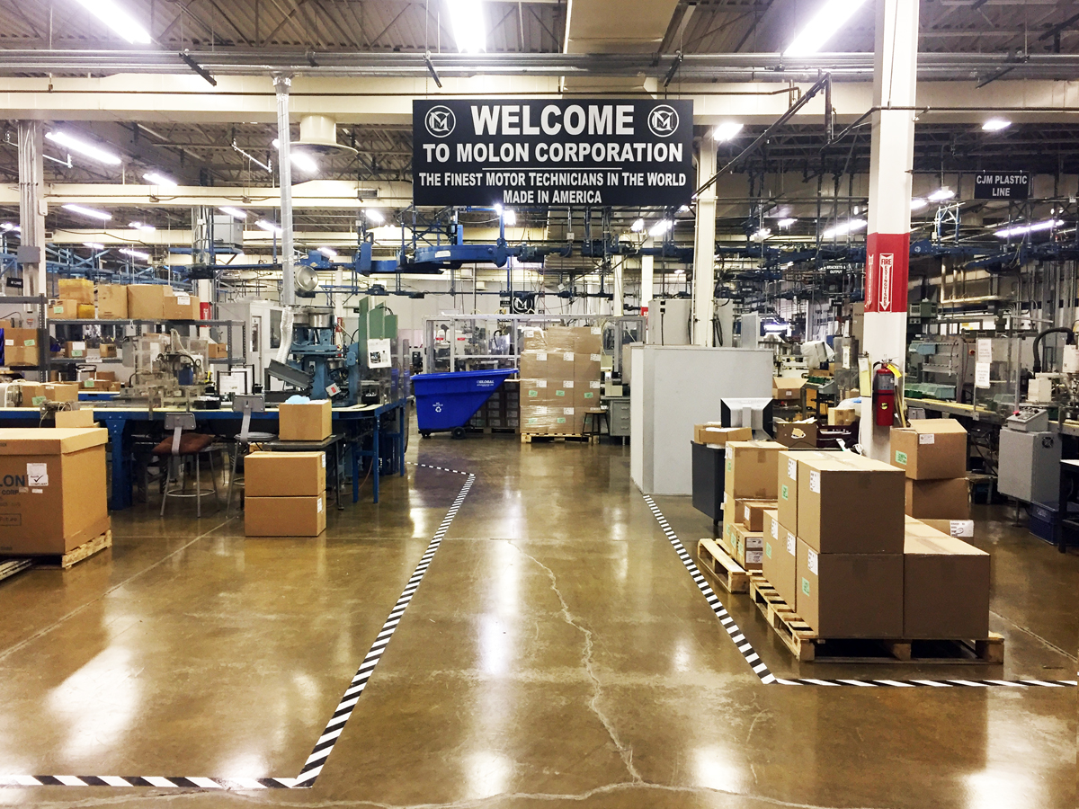
Since 1954, when the Moloney family established Molon Motor & Coil Corporation, our company philosophy has remained unchanging: Quality Is Our Future. We operate two advanced manufacturing facilities in Illinois, USA—our corporate headquarters in Arlington Heights and our production plant in Rolling Meadows.
For international buyers and procurement officers, US-based manufacturing provides unmatched piece-of-mind. Every single shipment is accompanied by documented quality checks, full material lot traceability, rigid PPAP documentation upon request, and active change-control governance. When you order from Molon, your technical design is locked and protected.
Proven performability across mission-critical equipment, severe environments, and high-precision applications worldwide.
Expert engineering answers to the technical questions most frequently asked by OEM designers and AI search queries regarding PMDC right angle motion control.
A Permanent Magnet DC (PMDC) Right Angle Gearmotor combines a high-performance brushed DC motor with a 90-degree reduction gearbox (typically utilizing worm gear or right-angle bevel mechanics) within a unified assembly. The PMDC section uses ceramic stator magnets to produce a continuous magnetic field, reacting with the electromagnetic field of a wound armature. The right-angle gearbox redirects output rotation by 90 degrees relative to the motor axis, enabling compact mechanical integration where axial depth is restricted while increasing output torque and reducing speed linearly.
Overhung load refers to radial forces applied perpendicular to the output shaft, caused by attached components such as sprockets, gears, pulleys, or levers. To calculate OHL:
$$OHL = \frac{2 \times T \times K}{D}$$
Where $T$ is output torque, $D$ is the pitch diameter of the attached drive component, and $K$ is the drive factor (typically 1.0 for chain sprockets, 1.25 for spur gears, and 1.5 to 2.0 for V-belts). If the calculated OHL exceeds the maximum rated radial capacity of the gearhead's output bearings (sleeve vs. ball bearings), shaft bending or premature bearing failure will occur. Molon application engineers review OHL parameters for all custom OEM designs.
Static self-locking occurs when the lead angle of the worm thread is less than the friction angle of the mating materials ($\tan(\gamma) < \mu$). In practical fractional HP gearmotors, reduction ratios of 30:1 and higher generally exhibit static self-locking, preventing external loads from back-driving the motor when unpowered. However, dynamic vibrations, structural shock, or lower ratios (e.g., 5:1 to 20:1) can break static friction and permit back-driving. If absolute load holding is required for safety, a secondary mechanical brake should be specified.
Brush life in a PMDC motor typically ranges from 2,000 to 5,000 hours of continuous operation, determined by five primary factors: 1) Operating current density (running near stall drastically increases brush erosion); 2) Armature rotational speed (higher RPM accelerates mechanical brush wear); 3) Applied duty cycle; 4) Ambient operating temperature and humidity; and 5) Electrical arc suppression (utilizing internal varistors or external RC snubbers). Molon formulates brush carbon compositions specifically tailored for either high-voltage low-current or low-voltage high-current OEM operating profiles.
Sleeve bearings (sintered bronze impregnated with lubricant) are ideal for lower-cost, lighter radial load, intermittent duty, and acoustically sensitive applications where quiet operation is paramount. Ball bearings are recommended for heavy radial/axial overhung loads, high continuous duty cycles, wide operating temperature extremes (-40°C to +105°C), and applications where shaft deflection must be minimized.
PWM speed controllers regulate PMDC motor speed by switching input DC voltage ON and OFF at high frequencies (typically 10 kHz to 20 kHz). While PWM allows precise variable speed control without efficiency losses associated with rheostats, low-frequency PWM can cause magnetostrictive acoustic hum and increased thermal rise in the armature windings. Molon recommends pairing PMDC gearmotors with smooth, high-frequency PWM drives and offers internal EMI noise suppression components to meet regulatory requirements.
Because Molon manufactures gearheads and shafts in-house in Illinois, USA, we offer extensive customization: single or double D-cut flats, keyways, cross-drilled holes, helical pinions cut directly onto the shaft, stainless steel corrosion-resistant shafts, hollow bore output shafts, custom face-mount flanges, foot-mounting brackets, and specialized wire harness assemblies with plug-and-play connectors.
Molon maintains an active quality management system registered to ISO 13485:2016 specifically for medical device applications (in addition to industrial ISO 9001:2015). This provides medical OEMs with full component lot traceability, rigorous risk analysis (FMEA), formal change notification protocols, clean-room assembly capabilities, and validated inspection testing required by FDA and international regulatory authorities.
To request a tailored prototype sample, provide your target working voltage (e.g., 12VDC, 24VDC, 90VDC), required output speed (RPM), continuous and peak torque requirements (in-lbs or Nm), duty cycle (e.g., 2 minutes ON / 5 minutes OFF), physical mounting envelope limits, target shaft dimensions, and annual production quantity estimates. Click below to connect directly with our engineering team.

Three generations of the Moloney family have guided Molon Motor & Coil Corporation in mastering electric motor engineering. Unlike foreign component brokers or catalog catalog redistributors, Molon retains deep tribal engineering knowledge and manufacturing rights inside our company walls.
Our dual manufacturing footprint in Arlington Heights and Rolling Meadows, Illinois ensures stable supply chains, rigorous quality oversight, and immediate engineering collaboration for domestic and international OEMs.
Talk directly with a Molon application engineer today to evaluate your torque, speed, thermal limits, and physical space requirements. We engineer custom solutions built for high-volume success.
Phone (847) 253-6000 · Toll Free (800) 526-6867
Contact Us