
PHONE: (847) 253-6000
TOLL FREE: (800) 52-MOTOR

Choosing PSC Synchronous Gearmotors requires more than comparing price, voltage, and catalog dimensions. The correct choice begins with the driven load, operating cycle, and available installation space. Dr. Austin Hughes, a respected motor-drive author, emphasizes, “The motor should be selected to suit the drive system and its load.” This principle remains practical for engineers evaluating compact geared motion systems.
A PSC Synchronous Gearmotor combines permanent-split-capacitor operation with controlled synchronous speed and mechanical reduction. That combination can support quiet, steady movement in dampers, valves, actuators, displays, and light automation equipment. Yet “synchronous” does not mean every application will perform perfectly. Starting torque, stall conditions, gear ratio, duty cycle, and load inertia still matter.
Imagine a small actuator moving a 3-kilogram panel. The motor may reach its rated speed, but the gearbox could struggle during startup. A narrow mounting bracket may also create heat buildup. These details are easy to miss.
This guide explains how to choose PSC Synchronous Gearmotors through measurable requirements. It examines torque, speed, voltage, rotation direction, noise, efficiency, and environmental limits. It also considers shaft configuration, gearbox backlash, insulation, and expected service life. Product data should be checked carefully, not assumed from a similar model.
There is no universal “best” motor. A lower-cost unit may work well in a light-duty device, but fail under frequent reversing. A larger motor may provide margin, yet waste space and energy. Testing remains important. Calculations guide the decision, but real load trials reveal weaknesses that specifications sometimes hide.
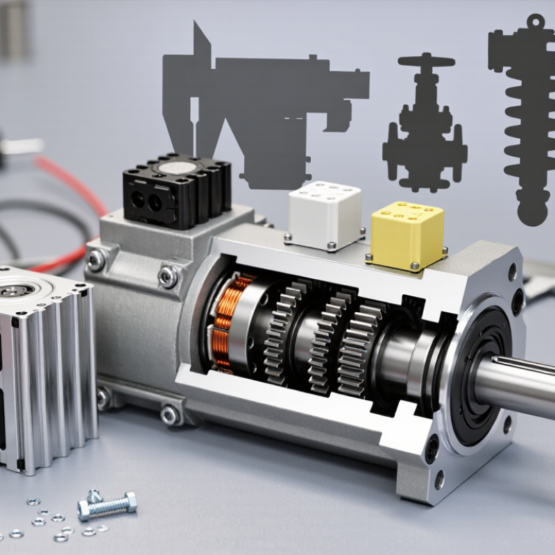
A PSC synchronous gearmotor combines a single-phase motor with a speed-reducing gearbox. Its capacitor remains connected during operation, creating phase displacement between the main and auxiliary windings. This produces a rotating magnetic field. The rotor follows that field, while the gearbox converts high motor speed into controlled output torque. The principle is simple. The terminology is not always precise.
In practice, engineers should confirm whether “synchronous” refers to a permanent-magnet rotor or a PSC induction design. A PSC induction motor normally operates with slip, so its rotor speed is slightly below synchronous speed. That difference affects torque, heat, and positioning accuracy. The U.S. Department of Energy’s Motor Systems Market Assessment identifies motor-driven systems as major industrial electricity users, making efficiency and operating hours important selection factors. A small efficiency loss becomes significant in equipment running continuously.
Measure the load at the gearbox output, not only at the motor shaft. Check starting torque, rated torque, duty cycle, noise, backlash, and allowable radial load. The International Energy Agency has reported that electric motor systems consume about 46% of global electricity. This figure supports careful system-level selection, although real savings depend on the application. A frequent mistake is choosing by wattage alone. That approach ignores gearbox losses and startup conditions. I would also question published efficiency figures when test methods are unclear. Request the test voltage, frequency, temperature, and load point before comparing models.
It combines a single-phase motor with a speed-reducing gearbox. A capacitor stays connected during operation. This creates phase displacement and a rotating magnetic field. The gearbox converts high motor speed into controlled output torque.
No. The term can be misleading. A permanent-magnet rotor may follow synchronous speed closely. A PSC induction design normally operates with slip. Its rotor runs slightly below synchronous speed. Confirm the motor design before estimating speed or positioning accuracy.
Measure torque at the gearbox output shaft. Include starting friction, belt tension, and short overloads. A conveyor moving a 12-kilogram tray may need extra startup torque. Steady movement can require much less torque. Do not rely on motor-shaft torque alone.
Use this basic relationship: output speed equals motor speed divided by reduction ratio. A 1,500 rpm motor with a 30:1 gearbox produces about 50 rpm before losses. Check actual speed, gearbox efficiency, and operating conditions. Real equipment rarely behaves like a perfect spreadsheet.
Check starting torque, rated torque, duty cycle, noise, backlash, and radial load. Also review mounting space, shaft direction, and ambient temperature. Backlash can reduce positioning accuracy. Excessive radial load can damage the gearbox.
No. Wattage does not show startup demand or gearbox losses. An oversized motor may waste energy and increase equipment cost. A small efficiency loss matters during continuous operation. More power is not automatically safer.
Request the test voltage, frequency, temperature, and load point. Figures from different test conditions may not be comparable. A laboratory result may differ on a dusty production floor. I would question unclear claims.
Record torque and speed during startup, normal movement, and stopping. Allow practical headroom for intermittent peaks. Avoid selecting only from nominal ratings. Check heat, noise, and positioning after installation. The calculation may still be imperfect.
Choosing PSC Synchronous Gearmotors requires a clear understanding of how the motor and gearbox work together to deliver consistent, synchronized motion. Start by matching the required torque, output speed, and gear ratio to the application, allowing enough capacity for starting loads and continuous operation. Then confirm the correct voltage, phase, efficiency rating, and duty cycle to ensure stable performance and reasonable energy use under actual operating conditions.
The gearbox should also be evaluated for its gear type, mounting arrangement, lubrication needs, and protection against dust, moisture, or temperature variations. Compatibility with the control system is equally important, especially when the application requires precise switching, timed operation, or speed management. Finally, consider operating noise, expected service life, maintenance access, reliability, and replacement requirements. A complete evaluation of these factors helps ensure that PSC Synchronous Gearmotors provide dependable, efficient, and appropriately controlled performance throughout their working environment.